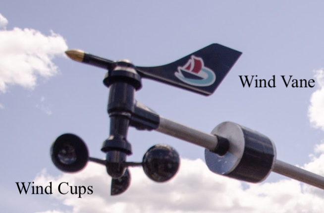
Our anemometer is a Davis Vantage Pro 2. It has a wind vane to measure wind direction and wind cups to measure wind speed as shown below.

See the datasheet or user manual for specific details regarding the assembly or use of the anemometer. Here I’ll give an introduction to how we retrieve and use the data from the anemometer.
The anemometer has four wires as shown in the table below.
| Wire | Connection |
|---|---|
| Red | Ground |
| Yellow | Power to wind direction sensor |
| Green | Wind direction output |
| Black | Wind speed contact closure to ground |
Note that the colors used are extremely unusual, especially using red for ground. This is just one of several very strange design choices made by the fine people at Davis Instruments. Some of this stems from the fact that the anemometer that we use as a stand-alone device is meant to be a replacement part on an entire weather station setup.
Wind Direction Sensor
The output from the wind direction sensor is given in analog protocol, meaning that the output is a just a voltage within some range. In this case, the range is from ground (0V) to the voltage of the power input (the logic level of the microcontroller, usually 3.3V). We take this voltage and map it to a value in [0, 360) degrees where 0V corresponds to 0 degrees, etc.
Wind direction tends to be prone to noise. To filter this out, we have historically used a weighted average of the current wind direction measurement and previous measurements as the wind direction parameter in the sailing algorithm.
Another thing to note is that the wind direction output that we recieve is relative to the angle of the sail (since the wind vane is positioned on the sail) while the wind direction that we use in the algorithm is with respect to north. To account for this, we calculate the wind direction with respect to north as the wind angle we measure + the sail angle with respect to the boat + the boat heading with respect to north.
Wind Speed Sensor
It’s worth noting that measuring the wind speed is only necessary if the polar diagram used to calculate the optimal angle of attack is not monotonically increasing in wind speed. The simplified polar diagram that we are using can definitely be used without knowing wind speed, so it’s probably best just to not use wind speed at all. However, just in case it’s ever needed, I’ve suffered to figure this out so you don’t have to.
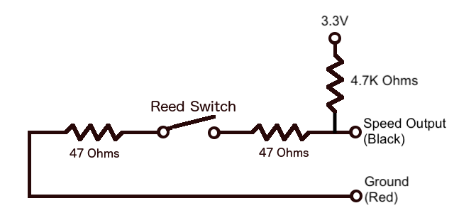
The documentation provided for the anemometer includes this nowhere (thanks Davis Instruments!), but the wind speed circuit is NOT connected to the power input for the wind direction sensor. If you miss this, you might spend days in the lab wondering why your output signal is so weak and noisy. No, it’s not because the cable is so long; the o-scope isn’t broken either. You just need to put a pull-up resistor on the wind speed output (see circuit below).

The output is a series of pulses. One pulse corresponds to one rotation of the wind cups about their axis. The easiest way to receive this is to use an interrupt pin on a rising edge. The specifics of configuring this depend on the microcontroller used. Track the time of the current pulse and the previous pulse (or more if you want a better average) and use the time difference to calculate the wind speed according to the only useful thing provided in the datasheet, this formula: speed (mph) = P * 2.25 / T, where P is the number of pulses recorded (typically 1) and T is the time period in which those pulses were recorded. You’ll probably want to convert this from mph to m/s.
Again, I’ll warn that this should only be implemented if necessary, otherwise it’ll be a waste of time and resources.